
Designing an inclined belt conveyor in 2026 requires more than selecting a motor and estimating belt length. Incline angle, material density, belt speed, capacity, and discharge height must work together. A small error can create noticeable problems at the loading point. Material may roll backward. Spillage may increase. Motor demand can rise unexpectedly.
This guide introduces a practical Inclined Belt Conveyor Design Calculation method for engineers, plant managers, and equipment buyers. It explains how to estimate conveyor capacity, horizontal and vertical forces, belt tension, power requirements, and suitable safety factors. Real operating details matter, including wet aggregate, uneven feeding, belt cleats, idler spacing, and frequent starts. A conveyor carrying crushed stone behaves differently from one moving packaged cartons.
The calculator can provide a useful preliminary estimate, but it cannot replace field measurements or professional review. Assumptions still matter. Friction values may change with dust, moisture, temperature, and belt condition. Even reliable formulas need careful interpretation. That is the point. Users should compare calculated results with supplier data, motor curves, structural limits, and applicable workplace standards before final approval. A conservative design may cost more initially, yet it can reduce slipping, overloads, unplanned downtime, and premature belt wear. The method is intentionally practical, but not perfect; unusual materials, steep inclines, or complex transfer arrangements deserve a detailed engineering assessment. Real conveyors often reveal issues that spreadsheets miss.
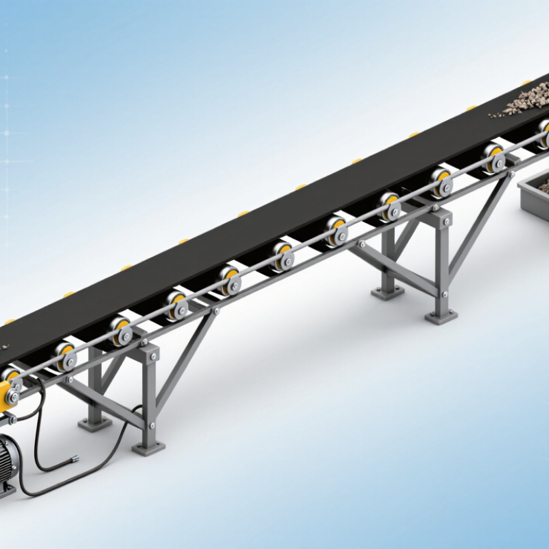
A dependable inclined belt conveyor design calculator begins with measured inputs, not guesses. Capacity should state the required material flow, such as 80 tonnes per hour. Record whether this value is continuous or only a short-term peak. Speed affects loading, spillage, and belt wear. Choose it alongside belt width, not separately. A narrow belt may carry the load, but it can create unstable material piles. Small assumptions matter.
Lift is the vertical distance between loading and discharge points. Do not confuse it with the conveyor’s total length. Incline angle also affects rollback risk, power demand, and material retention. Density requires care. Use bulk density, not the solid material density shown in a handbook. Moisture, particle size, and packing can change it during operation. The calculator should flag unrealistic combinations, such as high capacity on a very narrow belt. Experienced engineers compare calculated power with site conditions, including transfer points and startup loads. I once treated a dry material as stable, but humidity changed its flow noticeably. That mistake required a wider loading zone. Rechecking every input improves reliability, although the first estimate may still need revision. A practical design leaves room for imperfect data.
| Design Input | Symbol | Unit | Example Value | Typical Design Range | Design Basis and Practical Notes |
|---|---|---|---|---|---|
| Required Mass Capacity | Q | t/h | 80 | 5–500 | Use the continuous operating rate. Add a suitable design margin, commonly 10–15%, for surges and loading variation. |
| Belt Speed | v | m/s | 1.25 | 0.5–3.5 | Lower speeds reduce dust, segregation, and material degradation. Higher speeds can increase capacity but require careful loading and containment. |
| Belt Width | B | mm | 650 | 400–1,200 | Select width from the required cross-sectional load, material lump size, skirt clearance, and the applicable troughing arrangement. |
| Horizontal Conveyor Length | Lh | m | 24 | 5–150 | The horizontal projection is used with lift to determine the conveyor incline and the overall belt path. |
| Vertical Lift | H | m | 7.0 | 1–30 | Measure the vertical elevation difference between the loading and discharge points, excluding transfer chutes unless they are part of the design scope. |
| Incline Angle | θ | degrees | 16.3 | 0–20 | Calculated using arctan(H ÷ Lh). The permissible angle depends on material friction, moisture, particle size, and whether cleats or a profiled belt are used. |
| Bulk Density | ρ | t/m³ | 1.60 | 0.35–2.20 | Use loose bulk density at the loading point. Compaction, moisture, and particle distribution can substantially change the effective value. |
| Maximum Lump Size | dmax | mm | 75 | 5–300 | The largest particle affects loading-zone design, belt width, idler spacing, impact-bed selection, and the required skirt-board clearance. |
| Material Moisture | M | % by mass | 4 | 0–25 | Moisture influences adhesion, carryback, flowability, effective friction, and the maximum practical incline angle. |
| Troughing Idler Angle | α | degrees | 35 | 20–45 | A larger trough angle increases carrying capacity but may affect belt training, transition length, and suitability for sticky or fragile materials. |
| Design Capacity with Margin | Qd | t/h | 92 | Q × 1.10–1.15 | Example calculation: 80 t/h × 1.15 = 92 t/h. This value should be used for preliminary belt and drive sizing. |
| Actual Inclined Belt Length | L | m | 25.0 | Calculated | Calculated using √(Lh² + H²). Example: √(24² + 7²) = 25.0 m, before adding transition or take-up allowances. |
| Estimated Material Volume Flow | V | m³/h | 50.0 | Calculated | Calculated from Qd ÷ ρ. Example: 92 ÷ 1.60 = 57.5 m³/h; use the design capacity rather than the nominal rate for equipment checks. |
Enter the vertical lift, conveyor length, and incline angle. Keep the angle between 10° and 18°. Define length carefully. It may mean belt centerline or horizontal distance. Check the site drawing afterward.
Use H = L × sin(θ). Here, H is vertical lift. L is belt centerline length. θ is the incline angle. A 12-meter belt at 15° lifts about 3.11 meters.
Use D = L × cos(θ). If horizontal distance is known, use L = D ÷ cos(θ). A 12-meter belt at 15° projects roughly 11.59 meters horizontally. Small errors matter.
No. Consider traction, cleaning access, material flow, and loading stability. Wet or uneven material may roll backward. The best angle on paper may fail in operation. That deserves a second look.
Use Q = 3,600 × A × v × ρ. Q represents mass flow. A is loaded cross-sectional area. v is belt speed. ρ is loose conveyed bulk density. Use consistent metric units.
It describes how bulk material settles on the moving belt. It is not the conveyor incline angle.
Poor loading, unstable piles, and material rollback can reduce capacity. Spillage may occur near transfer points or skirt edges. Leave practical freeboard. Measure loose conveyed density from a representative sample. A laboratory value may mislead.
Compare required drive traction with available pulley traction. Include belt mass, material load, friction, pulley diameter, and acceleration. Check loaded starts, not only steady running. Moisture, dust, and low wrap can reduce traction. Do not hide uncertainty.
Divide available belt strength by peak operating tension. Use the lower rating between the belt and its splice. Consider jammed material, uneven loading, temperature, and wear. The splice is easy to overlook. That mistake can matter.
Check capacity, tracking, material throw, pulley speed, vibration, and guarding. Run the empty belt first. Then perform a controlled loaded run. Record tension measurements. A small tracking error can damage an edge quickly. The first calculation may still be wrong.
This guide presents a practical Inclined Belt Conveyor Design Calculation method for selecting and checking the main operating parameters of an inclined conveyor. It begins by defining the required capacity, belt speed, width, vertical lift, material density, and incline angle. Using the lift, conveyor length, and a recommended 10°–18° incline range, the calculation establishes the conveyor geometry and provides a foundation for reliable equipment sizing.
The method then estimates material-carrying capacity from the effective loading area and a 37.5° surcharge angle. Required drive power is determined by combining the power needed to raise the material, conveyor resistance, and a drive efficiency of 0.96. Final checks cover belt tension, traction and slip conditions, an appropriate safety factor, and the maximum allowable operating speed. Together, these steps help produce a balanced, efficient, and safe conveyor design suitable for consistent material handling performance.